How To
Lines Plus for Unreal · How To
This chapter explains the most common tasks step by step. You do not need to write code for any of them. The first sections use a line placed in a level, and the last ones draw lines from a Blueprint.
How to place a line in a level
- Open the Place Actors panel. If you do not see it, select Window > Place Actors in the main menu.
- Type Lines Plus in the search box of the panel.
- Drag Lines Plus from the panel into the level. A white straight line appears. It has two points.
- Move the actor with the gizmo, as any other actor.
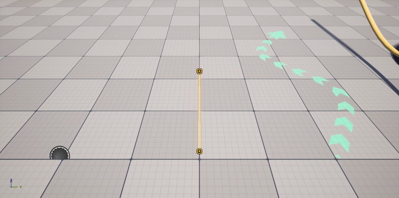
With the line selected, the Details panel shows its settings. Click the Lines Plus button at the top of the panel to see only the settings of the plugin. The header shows the number of points and the length of the line.
How to move, add and delete points
- Select the line. Yellow rings appear on its points in the viewport.
- Click a point to select it, then drag the arrows of the gizmo to move it.
- To add a point, right-click a point and select Add Point. The new point appears between that point and the next one.
- To delete a point, right-click it and select Delete Point, or select it and press the Delete key. A line always keeps two points at least.
You can also type the position of each point: in the Details panel, open Points. Click the + button next to it to add a point at the end. The new point continues the line in the direction of its last side. The positions are relative to the actor, so the whole line moves when you move the actor.
Enable Closed to join the last point with the first one. A closed line needs three points at least. Enable Smooth to draw a curve through the points.
How to change the look of a line
The look is in six groups under the settings of the line: Shape, Color, Pattern, Caps, Label and Animation. Click the name of a group to open it. The line shows each change at once.
| To get this | Do this |
|---|---|
| Another color | Open Color and click the Color box. |
| A wider line | Open Shape and raise Width. |
| A dashed or dotted line | Open Pattern and set Pattern to Dashed or Dotted. Dash Length and Gap Length change the size of the dashes and of the spaces. |
| Dashes that move | Set Pattern Speed to a value like 50. |
| An arrow at the end | Open Caps and set End Cap to Arrow. |
| Round ends | Set Start Cap and End Cap to Round. |
| A text along the line | Open Label and type the text in Label. |
| The length of the line | Open Label and enable Show Length. Enable Length Per Segment to see the length of each segment. |
| A soft light around the line | Open Color and raise Glow Width to 2 or 3. |
| A line seen behind walls | Open Color and enable Visible Through Walls. Enable Use Hidden Color to give another color to the hidden part. |
| The same width on the screen at any distance | Open Shape and set Width Unit to Screen Pixels. |
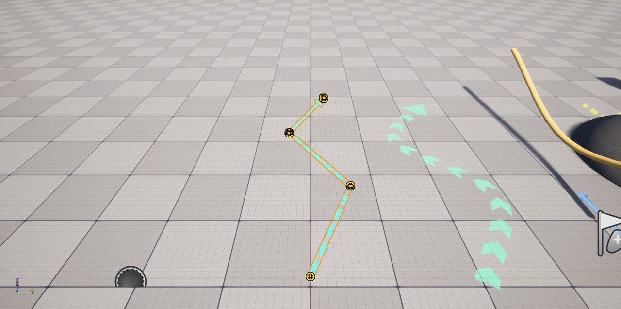
Five common lines
Each recipe starts with a new line placed in the level.
A path on the ground with arrows
- Add points to the line until it has the shape of the path, and enable Smooth.
- In Shape, set Shape to Flat Ribbon and Width to 26. The line now lies flat, like paint on the ground.
- In Pattern, set Pattern to Chevrons, Dash Length to 22, Gap Length to 24 and Pattern Speed to 70.
- In Caps, set End Cap to Arrow.
- Move the actor a little above the ground, so the ground does not hide the line.
A cable
- Give the line three points: the two ends up and the middle point lower. Enable Smooth.
- In Shape, set Shape to Tube and Width to 10.
- In Color, set Blend to Opaque. Then enable Lit and Cast Shadow. The tube now receives the light of the level and casts a shadow.
A line that follows the ground
- Place the line over a hill or over any uneven ground. The ground needs collision, as the basic shapes and the landscapes have.
- In Shape, enable Snap to Ground. The line lies on the ground between its points.
- Ground Offset is the height of the line above the ground. Lower Ground Spacing to follow the ground better.
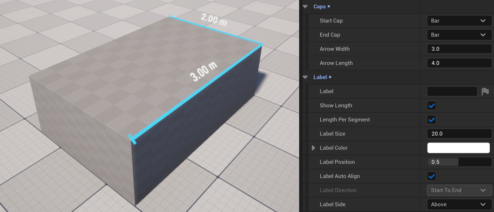
A measure line
- Move the two points of the line to the two places that you want to measure, for example two corners of a wall. Add more points to measure a path with several segments.
- In Caps, set Start Cap and End Cap to Bar.
- In Label, enable Show Length. The length appears next to the line, in meters. Enable Length Per Segment to see the length of each segment.
- Label Size changes the size of the text, and Label Side places it above or below the line.
A line that draws itself
- In Animation, set Draw Duration to 2.
- Check that Draw on Begin Play is enabled in the settings of the line.
- Press Play. The line draws itself from its first point to its last point in two seconds. The animation plays in the game, not in the editor.
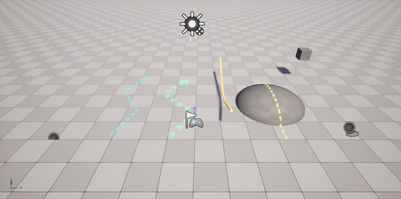
How to share a look between lines
A Lines Plus Style is a file that holds a look. Many lines can use the same style, and a change in the style changes all of them.
- Select a line. In the Details panel, open the list of Style Asset.
- Under Create New Asset, select Lines Plus Style. Choose a folder and a name.
- The new style is assigned to the line. Its settings appear in the same six groups.
- Select another line and choose the same style in its Style Asset list.
- Double-click the style in the Content Browser to open it in its own window. The window shows the settings and a preview of a line with that look.
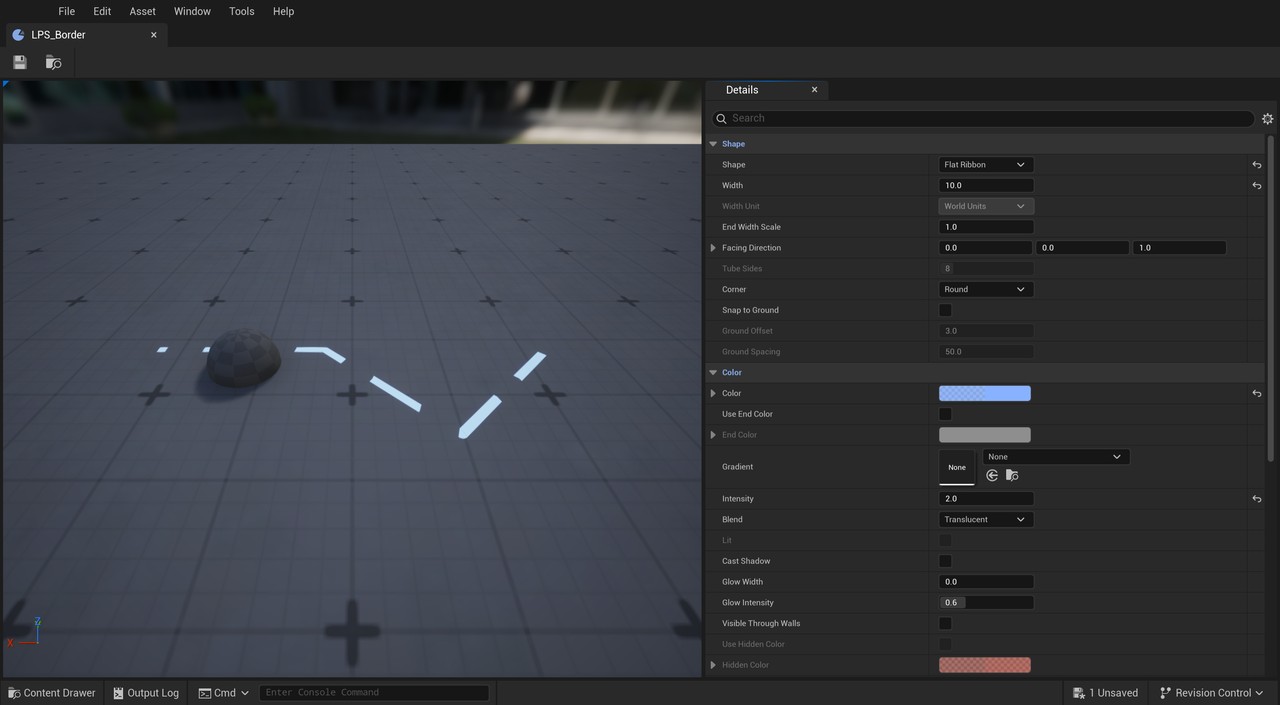
The line of the preview has straight sections, corners and two ends, so it shows every setting. It crosses a small obstacle that shows the hidden part of the line and the ground snap.
How to draw a line from a Blueprint
A Blueprint can draw lines while the game plays. This example draws one line when the game starts.
- In the Content Browser, click Add, select Blueprint Class and then Actor. Name it BP_MyLine and double-click it.
- Open the Event Graph tab. It already has the node Event BeginPlay.
- Right-click an empty place of the graph, type Draw Line and select it in the Lines Plus category.
- Drag from the white arrow of Event BeginPlay to the white arrow at the left of Draw Line.
- Type the two ends of the line in Start and End. They are positions in the world, for example 0, 0, 100 and 300, 0, 100.
- Drag from the Style pin to an empty place, type Make Simple Style and select it. Choose a Color and a Width in the new node.
- Click Compile and then Save.
- Drag BP_MyLine from the Content Browser into the level and press Play.
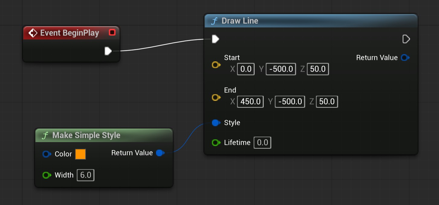
For a look with more settings, drag from the Style pin and select Make Lines Plus Style. This node has every setting of the look.
How to join two actors with a line
The node Draw Link draws a line between two objects. The line follows them when they move, and it is removed when one of them is destroyed. This example joins the Blueprint actor with another actor of the level.
- Create a Blueprint as in the previous section and name it BP_MyLink.
- In the My Blueprint panel, click + next to Variables. Name the variable Target. In the Details panel, set Variable Type to Actor, Object Reference, and enable Instance Editable.
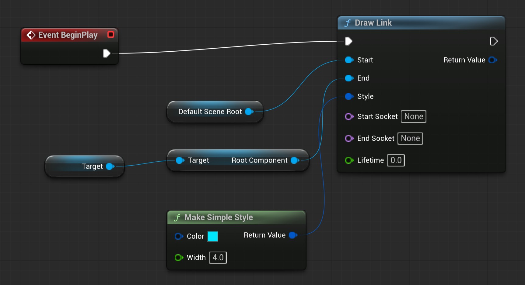
- In the Event Graph, add the node Draw Link and connect Event BeginPlay to it.
- Drag DefaultSceneRoot from the Components panel into the graph and connect it to Start.
- Drag the variable Target into the graph and select Get Target. Drag from its pin, type Get Root Component and select it. Connect the result to End.
- Add a Make Simple Style node to the Style pin, as in the previous section.
- Click Compile and Save. Drag BP_MyLink into the level.
- Select it in the level. In the Details panel, set Target to another actor of the level, for example a cube. Press Play.
How to change or remove a Blueprint line
Every draw node returns a value in its Return Value pin. This value is the handle of the line. Keep it to change the line later.
- Drag from Return Value to an empty place and select Promote to Variable. Name the variable My Line.
- Later, for example after a key press, add one of these nodes and connect My Line to its Line pin.
| Node | What it does |
|---|---|
| Set Line Color, Set Line Width | Change the color or the width. |
| Set Line Ends | Moves the two ends of a straight line. |
| Play Draw | Draws the line from start to end in a number of seconds. |
| Set Line Visible | Hides the line or shows it again. |
| Remove Line | Removes the line. |
A line can also remove itself: the draw nodes have a Lifetime pin, in seconds. With a lifetime of 0 the line stays.
Other draw nodes work in the same way: Draw Polyline for a list of points, Draw Curve for a smooth curve, Draw Circle, Draw Box and Draw Grid for shapes, and Draw Trajectory for the path of a projectile. See Blueprint Nodes for the full list.
How to aim with the mouse
This example draws the path of a projectile from the character to the point under the mouse cursor and updates it in each frame. It uses the Top Down template of the engine, and it works in the same way with any character.
- Open the Blueprint of the character, for example BP_TopDownCharacter in the folder TopDown > Blueprints. If the window shows only the default values, click Open Full Blueprint Editor. Then open the Event Graph tab.
- If the graph does not have the node Event BeginPlay, right-click an empty place, type BeginPlay and select Event BeginPlay.
- Add the node Draw Trajectory and drag from the white arrow of Event BeginPlay to the white arrow at the left of Draw Trajectory.
- Drag from the Start pin to an empty place and select Get Actor Location. Drag from the Style pin and select Make Lines Plus Style. In this node, set End Cap to Arrow, Pattern to Dashed and Pattern Speed to 50.
- Drag from Return Value of Draw Trajectory, select Promote to Variable and name the variable AimLine.
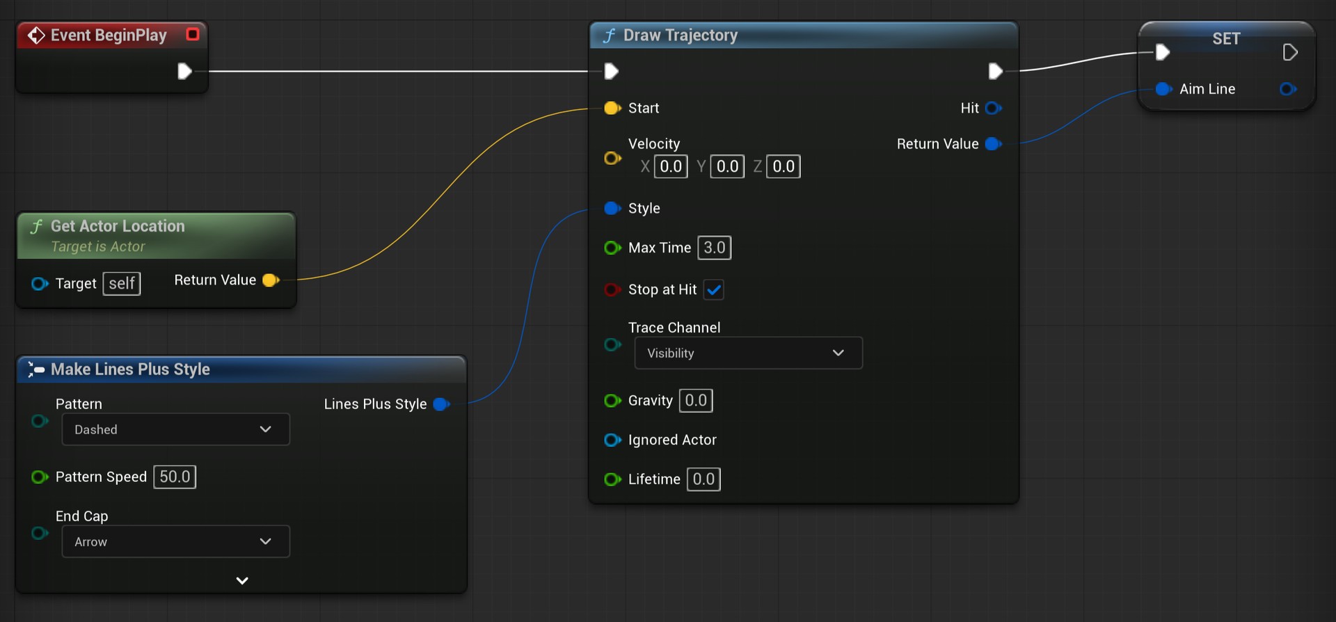
In the image, the node Make Lines Plus Style shows only the settings that the example changes. To hide the other pins, select the node and clear them under Pin Options in the Details panel.
- Add the node Event Tick. It runs in each frame.
- Add the node Get Player Controller. Drag from its Return Value and select Get Hit Result Under Cursor by Channel. Keep Trace Channel on Visibility. This node has no white arrows, so it does not need a connection to Event Tick.
- Drag from its Hit Result pin and select Break Hit Result. Its Location pin is the point under the cursor.
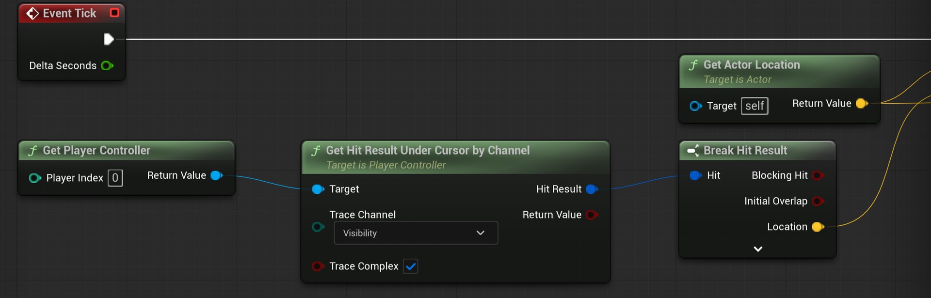
- Add the node Suggest Projectile Velocity Custom Arc and connect the white arrow of Event Tick to it. Connect a new Get Actor Location to Start Pos, and Location of Break Hit Result to End Pos.
- Drag from the white arrow at the right of Suggest Projectile Velocity Custom Arc and select Update Trajectory. Drag the variable AimLine from the My Blueprint panel, select Get and connect it to Line. Connect Get Actor Location to Start and Out Launch Velocity to Velocity.
- Drag from the Ignored Actor pin, type self and select Get a reference to self. The path then does not stop on the character.
- Click Compile and Save, and press Play. Move the mouse: a dashed path with an arrow goes from the character to the cursor.
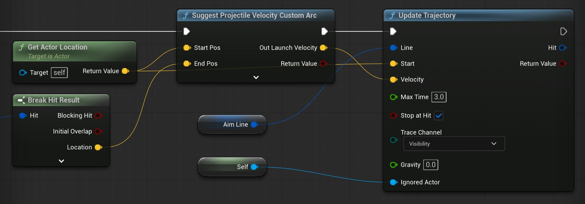
Use Play and not Simulate, because a simulation has no player and no cursor. If you see two characters with two paths, a copy of the character is placed in the level: select it in the Outliner and delete it. The game creates the character of the player at the Player Start.
Suggest an improvement
Help us improve this documentation page.