3D Terrain Graph
intermediate conceptsVoxel Play 4 · World Architecture
The Terrain Graph Editor is a visual, node-based tool for designing procedural terrain in Voxel Play 4. Instead of writing code, you connect nodes on a canvas to build a signal-processing pipeline that generates, transforms and blends values into a complete voxel world with biomes, caves, water and vegetation.
This page is a comprehensive reference for the Graph Editor window, all toolbar options, and every available node type with its parameters and formulas.
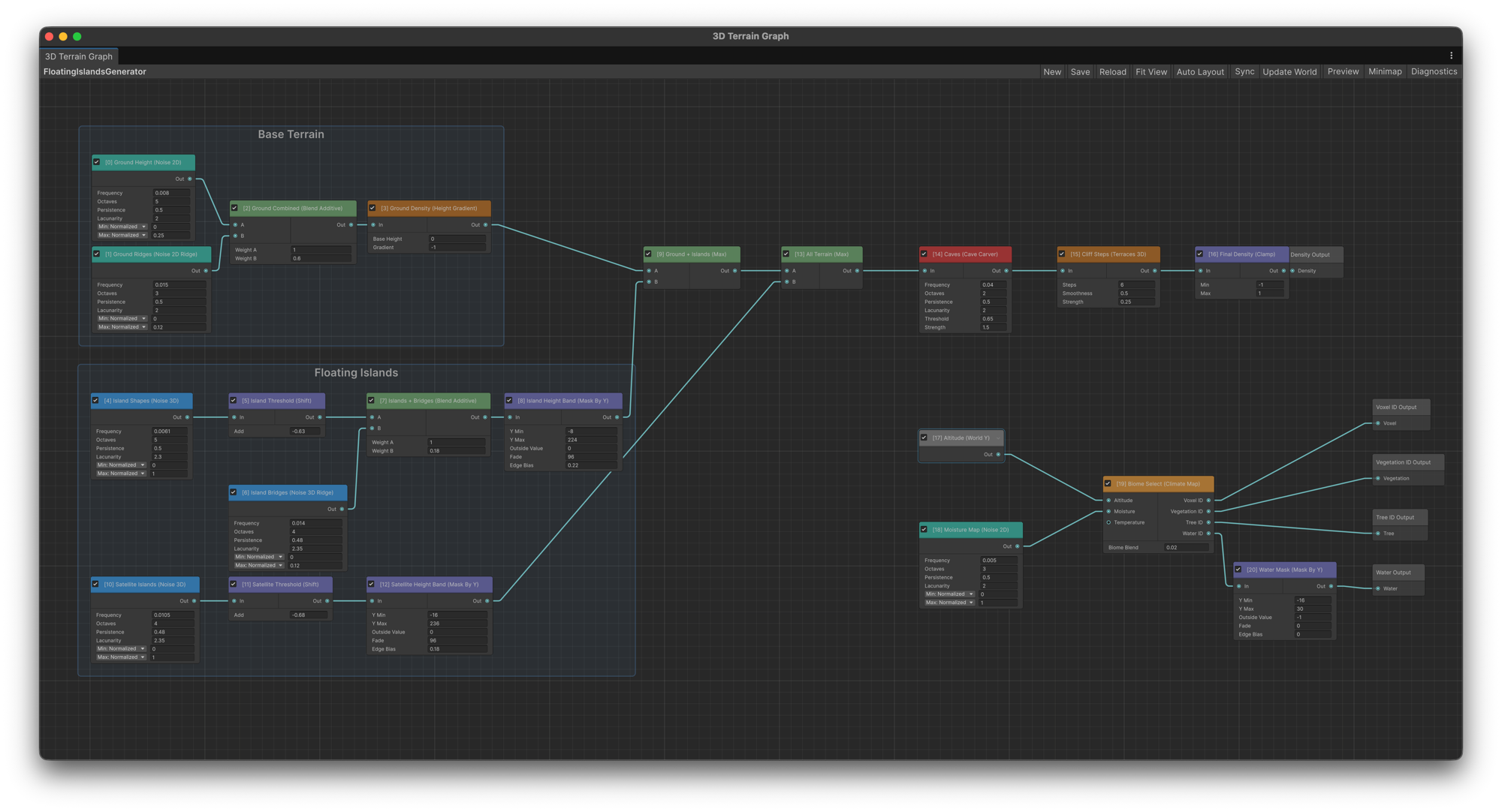
Two Graph Systems
Voxel Play 4 includes two terrain graph editors:
| Terrain Graph (2D) | 3D Terrain Graph | |
|---|---|---|
| How it works | Generates a heightmap (altitude + moisture). Terrain is solid below the height, air above. | Generates a 3D density field. Terrain exists wherever density > 0, enabling caves, overhangs and floating islands. |
| Outputs | Altitude, Moisture | Density, Voxel ID, Vegetation ID, Tree ID, Water ID |
| Generator asset | Multi-Step Terrain Generator | 3D Terrain Generator |
| Best for | Classic heightmap worlds, simpler setup | Complex worlds with caves, arches, volumetric features |
Getting Started
This video builds a 3D Terrain Graph from scratch, step by step:
Step 1: Create a Generator Asset
In the Project window, right-click and choose:
- Create > Voxel Play > Terrain Generators > Multi-Step Terrain Generator for 2D
- Create > Voxel Play > Terrain Generators > 3D Terrain Generator for 3D
Name it something descriptive (e.g. "MyWorldTerrain").
Alternatively, while the Terrain Generator field of your World Definition is empty, click the Create button next to it. This creates a 3D Terrain Generator with a flat starter graph in a Generators folder next to the World Definition and assigns it to the world.
Step 2: Open the Graph Editor
Select the generator asset and click the button at the top of its Inspector: Open in 3D Graph Editor for a 3D Terrain Generator, or Open in Graph Editor for a Multi-Step Terrain Generator.
Step 3: Build Your Graph
Right-click in the graph area and choose Create Node (or press Space with the canvas focused) to open the node search menu. Add nodes by category:
- Start with a noise sampler (e.g. Noise 3D, Sample Fractal) to generate base terrain shape
- Add a Height Gradient node (3D only) to define where solid meets air
- Use math and blend nodes to combine, scale and shape the output
- Pass the density through a Cave Carver to hollow out underground areas
- Connect a Climate Map node for biome-aware voxel selection
- Wire the final result to the output terminals on the right side of the graph
Step 4: Assign to Your World
In your World Definition asset, set the Terrain Generator field to your generator asset. Press Play to see the result.
Window Layout

The editor window is divided into the following areas:
Toolbar
The top toolbar contains buttons and toggles:
| Control | Type | Description |
|---|---|---|
| New | Button | Creates a new terrain generator asset and opens it in the editor. |
| Reload | Button | Reloads the graph from the saved generator asset, discarding any unsaved changes. |
| Save | Button | Saves the current graph state to the generator asset. Also available via Ctrl+S / Cmd+S. |
| Auto Layout | Button | Automatically arranges all nodes in a clean layout based on their connections. |
| Fit View | Button | Zooms and pans the canvas so all nodes are visible. |
| Minimap | Toggle | Shows or hides the minimap overlay (top-left corner). |
| Preview | Toggle | Shows or hides the terrain preview panel. |
| Diagnostics | Toggle | Shows or hides the diagnostics panel that reports errors, warnings and info messages about the graph. |
| Sync | Toggle | When enabled, the scene world rebuilds automatically while you edit the graph. The editor samples the graph at five fixed points (altitude and moisture in the 2D graph, density in the 3D graph) and reloads the world only when one of those values changes, so edits that do not change the terrain at those points, such as changes to the Voxel, Vegetation, Tree or Water ID outputs of the 3D graph, are not applied until you press Update World. In the 3D graph, while a single node that feeds Density Output is selected, the scene shows the output of that node alone as density; click an empty area of the canvas to see the full graph again. Enabling Sync also turns on Render In Editor and performs an immediate world update. |
| Update World | Button | Manually reloads the currently loaded world using the current graph state. |
Canvas
The main area where nodes are placed and connected. Navigation:
- Scroll wheel: zoom in/out.
- Middle-click drag or Alt + drag: pan the view.
- Right-click on empty space and choose Create Node, or press Space: opens the node search menu.
- Click a node to select it. Shift+click or drag a selection box for multiple nodes.
- Delete / Backspace: delete selected nodes and connections.
- Ctrl+C / Ctrl+V: copy and paste selected nodes.
- Ctrl+Z / Ctrl+Y: undo and redo.
Minimap
A small overview in the top-left corner showing the full graph layout. Click or drag inside the minimap to navigate quickly to any part of the graph. Toggle its visibility with the Minimap button in the toolbar.
Preview Panel
The preview panel (bottom-right by default) renders a real-time visualization of the terrain produced by the current graph. It can be dragged to reposition and resized by dragging its edges.
The preview offers the following display modes:
| Mode | Description |
|---|---|
| Hillshade | Default mode. Shaded relief view of terrain elevation with simulated lighting; water areas shown in blue. |
| Heightmap | Color-coded altitude: blue for water, green for land, white for peaks. |
| Moisture | Visualizes the moisture output. Requires a Moisture Output connection in the graph. |
| Biomes | Colors each pixel based on the biome selected by the altitude/moisture combination. Requires a World Definition with biomes configured. |
| Horizontal Slice (3D only) | Cross-section of the density field at a given Y height. |
| Vertical Slice (3D only) | Side-view cross-section of the density field. |
Adjust the preview resolution (32-512 px) and, for the 3D slice modes, use the Slice Y slider to choose the cross-section height. The status bar at the bottom of the preview shows altitude range, coverage area, and water level. Click on the preview to inspect altitude and moisture values at a specific world position.
Diagnostics Panel
When enabled, the diagnostics panel appears at the bottom of the window. It shows real-time validation messages about your graph:
- Errors (red): issues that prevent the graph from producing valid output (e.g., disconnected output nodes, cycles).
- Warnings (yellow): potential problems that may cause unexpected results (e.g., unconnected input ports).
- Info (white): general information about the graph state.
Click on a diagnostic message to highlight the affected node in the canvas.
Working with Nodes
Creating Nodes
Right-click on the canvas and choose Create Node (or press Space with the canvas focused) to open the node search menu. Nodes are organized into five categories, each with a distinct color:
| Category | Color | Description |
|---|---|---|
| Samplers | Green | Generate initial terrain values from noise textures, fractal noise, Unity Terrain data, constants or random values. These nodes have no required inputs - they produce values from external sources or fixed data. |
| Math | Orange | Transform values using arithmetic, range manipulation, and terrain-shaping functions. Includes single-input operations (shift, clamp, remap) and dual-input operations (min, max, subtract, divide). |
| Blending | Purple | Combine two input values using additive or multiplicative blending with custom weights. |
| Filters | Yellow | Conditional operations: threshold comparisons, range tests, value replacement, and special-purpose masks. |
| Utilities | Gray | Helper nodes like Reroute for organizing complex connection layouts. |
Connecting Nodes
Each node shows input ports on the left and an output port on the right. To connect nodes, drag from an output port to an input port (or vice versa). Values flow through connections and are evaluated in topological order.
Port names vary by node type:
- Out: the single output port present on every step node.
- In: a single input for nodes that transform one value (e.g., Shift, Invert, Clamp).
- A / B: two inputs for dual-input operations (e.g., Blend Additive, Min, Max, Subtract).
- Value / Ref or Value / Mask: nodes like Fill and Beach Mask that carry a main value through while reading a separate reference input.
Output Nodes
In the 2D Terrain Graph, the graph has two special output nodes that cannot be deleted:
- Altitude Output: the final terrain height value (normalized 0 to 1). This value is multiplied by Max Height to determine the world altitude in voxels.
- Moisture Output: an optional secondary value used together with altitude for biome selection. If no connection is made to Moisture Output, the terrain generator falls back to the legacy moisture texture configured in the Inspector.
The 3D Terrain Graph exposes a different set of output terminals - see 3D Graph Outputs below.
Node Controls
- Enable/Disable toggle: the checkbox in the node title bar. Disabled nodes are dimmed and skipped during evaluation.
- Custom description: each node has a description field (right-click the node and choose Rename to set it). When set, it replaces the default operation name in the title bar, helping you label nodes by purpose (e.g., "Base Mountains", "River Mask").
- Collapse/Expand: click the node title to toggle parameter visibility.
Height Units
Many numeric parameters support three display modes via a dropdown next to the field:
| Unit | Description |
|---|---|
| Normalized | Raw graph value, typically in the 0..1 range. This is the internal representation. |
| Percentage | The normalized value multiplied by 100. Entering 50% is equivalent to 0.5 normalized. |
| Meters | Converts using the terrain generator's Max Height. For example, with Max Height = 255, entering 127.5 meters equals 0.5 normalized. |
The unit choice is purely a display convenience - the internal stored value is always normalized. Changing the unit dropdown converts the displayed number without altering the actual parameter.
Reroute Nodes
Reroute nodes are small pass-through dots available in the Utilities category (right-click > Add Reroute). They have one input and one output and simply forward the value. Use them to organize connection lines in complex graphs - route wires around obstacles or create cleaner visual paths. Reroute nodes can branch: a single input can feed multiple outputs.
Node Groups
In the 3D Terrain Graph, select several nodes, right-click and choose Create Group to wrap them in a titled box. Rename the group to label a stage of the graph (for example "Heightmap", "Caves" or "Climate") and move its nodes together. Right-click a group and choose Ungroup to dissolve it.
3D Graph Outputs
The 3D graph has five output terminals:
| Terminal | Type | Description |
|---|---|---|
| Density | Required | Volume density. Positive = solid voxel, negative = air, zero = surface. |
| Voxel ID | Optional | Biome index for selecting which block type to place (connects to biome array) |
| Vegetation ID | Optional | Biome index for grass/flower placement |
| Tree ID | Optional | Biome index for tree generation |
| Water ID | Optional | Biome index whose water voxel fills air at this position (falls back to the generator's Water Voxel). Values outside the biome array, such as -1, place no water. |
ID outputs reference the biome array in your World Definition. For example, if Voxel ID outputs 2, the engine uses the voxel definitions from biomes[2].
Performance
The graph evaluation includes automatic optimizations:
- Column caching - 2D nodes (noise that only depends on X/Z) are evaluated once per column and cached, avoiding redundant computation across the vertical axis. Up to ~10x speedup for 2D-heavy graphs.
- Multi-core parallelization - 3D evaluation uses
Parallel.Forwith per-thread workspaces. Typical ~5x speedup on modern CPUs. - All-air fast path - Chunks that produce only air are detected early and skipped entirely.
Tip: Prefer 2D noise nodes over 3D noise nodes when the result doesn't need to vary with altitude. The column cache only works for 2D nodes.
Min Island Width (Island Filter)
3D density fields can leave tiny floating islands wherever the noise barely crosses the surface threshold. The Min Island Width option on the 3D Terrain Generator (minIslandWidth, 0-64, default 0 = disabled) removes isolated solid clusters narrower than the given number of voxels across (their largest horizontal extent in X or Z).
- The filter is deterministic and applied consistently everywhere the terrain is evaluated: painted chunks, the distant Super Chunks LOD and detail generators.
- Only floating clusters are affected - columns connected to the ground are never removed.
- Very large components are always kept (the measurement is capped, fail-open), so the filter cannot eat real islands.
Node Reference
This section documents the core sampler, math, blending, filter and utility nodes with their parameters, input/output ports, and evaluation formulas. The 3D Terrain Graph adds volumetric nodes such as Height Gradient, 3D noise and the Cave Carver; the Node Reference page lists the complete node set.
Samplers (Green)
Sampler nodes generate initial terrain values. They have no required input connections.
Sample Height Map Texture
Reads a value from a repeating 2D noise texture. The red channel is used as the height value. Voxel Play 4 includes several noise textures in Resources/Worlds/Earth/Noise/, but you can provide your own.
| Parameter | Description |
|---|---|
| Noise Texture | The 2D texture to sample. The red channel provides the height value. |
| Frequency | Multiplier applied to world X/Z coordinates before sampling. Higher values make the pattern repeat more often (default: 0.1). |
| Offset | X/Z offset added to sampling coordinates before reading the texture. |
| Min | Lower bound of the remapped output range. |
| Max | Upper bound of the remapped output range (default: 0.5). |
Formula: output = sample(texture, x * frequency + offsetX, z * frequency + offsetY) * (max - min) + min
Sample Ridge Noise From Texture
Similar to Sample Height Map Texture but applies a ridge formula to the sampled value: 2 * (0.5 - abs(0.5 - value)). This produces sharper, more acute relief patterns - useful for generating rivers (when inverted) or pointy mountain ridges.
| Parameter | Description |
|---|---|
| Noise Texture | The 2D texture to sample. |
| Frequency | Sampling frequency multiplier. |
| Offset | X/Z offset added to sampling coordinates. |
| Min | Lower bound of the remapped output range. |
| Max | Upper bound of the remapped output range. |
Formula: ridged = 2 * (0.5 - abs(0.5 - sample)), then output = ridged * (max - min) + min
Sample Height Map Fractal
Generates procedural Perlin fractal noise without requiring a texture. This is the most flexible sampler for creating natural-looking terrain, as it combines multiple octaves of noise at different frequencies.
| Parameter | Description |
|---|---|
| Frequency | Base frequency of the fractal noise. Higher values produce more frequent variation. |
| Octaves | Number of fractal layers combined together (1-8). More octaves add finer detail. |
| Persistence | Amplitude multiplier from one octave to the next. Lower values reduce the contribution of higher octaves. |
| Lacunarity | Frequency multiplier from one octave to the next. Controls how quickly detail increases. |
| Offset | X/Z shift applied to the sampling coordinates. Give each noise node a different offset so several of them do not repeat the same pattern. |
| Min | Lower bound of the remapped output range. |
| Max | Upper bound of the remapped output range. |
Formula: output = fractalNoise(x, z, frequency, octaves, persistence, lacunarity) * (max - min) + min
Ridge Noise Fractal
Procedural ridge noise built from fractal Perlin noise, with no texture required. The fractal is inverted around its midpoint to produce sharp ridgelines: mountain chains, eroded crests and, once inverted, river valleys.
| Parameter | Description |
|---|---|
| Frequency | Base frequency applied to the procedural ridge noise. |
| Octaves | Number of fractal layers combined together (1-8). |
| Persistence | Amplitude multiplier applied from one octave to the next. |
| Lacunarity | Frequency multiplier applied from one octave to the next. |
| Offset | X/Z shift applied to the sampling coordinates, so two ridge nodes produce different ranges. |
| Min | Lower bound of the remapped output range. |
| Max | Upper bound of the remapped output range. |
Cellular Noise
Procedural cellular (Worley) noise, with no texture required. The plane is divided into cells around scattered feature points; the node outputs either the distance to the nearest cell centre or the border between cells.
| Parameter | Description |
|---|---|
| Frequency | Base frequency of the cellular pattern. Higher values pack more cells into the same area. |
| Mode | Cells outputs the distance to the nearest cell centre, useful for regions and plateaus. Edges outputs the borders between cells, useful for cracks, rivers and biome frontiers. |
| Jitter | How far cell centres wander from the grid (0-1). 0 is a regular grid, 1 is fully scattered. |
| Offset | X/Z shift applied to the sampling coordinates. |
| Min | Lower bound of the remapped output range. |
| Max | Upper bound of the remapped output range. |
Sample Height Map Unity Terrain
Reads height data from an existing Unity Terrain asset's heightmap. Useful for converting a hand-painted Unity terrain into a Voxel Play 4 world while combining it with procedural operations.
| Parameter | Description |
|---|---|
| Terrain Data | The Unity TerrainData asset to sample. |
| Frequency | Multiplier applied to world X/Z before sampling. Higher values repeat the terrain data. |
| Offset | X/Z offset added before reading the heightmap. |
| Min | Lower bound of the remapped output range. |
| Max | Upper bound of the remapped output range. |
Constant
Outputs a fixed constant value. Useful as a baseline height, a weight input, or any fixed parameter that other nodes can reference.
| Parameter | Description |
|---|---|
| Value | The constant value to output. Supports height units (Normalized/Percentage/Meters). |
Random
Outputs a deterministic pseudo-random value in the 0-1 range based on the world X/Z position. The same position always produces the same value, ensuring consistent terrain generation.
No parameters.
Math (Orange)
Math nodes transform incoming values. Single-input nodes have one In port. Dual-input nodes have A and B ports.
Shift
Adds a constant amount to the incoming value. The simplest way to raise or lower the entire terrain.
| Port/Parameter | Description |
|---|---|
| In (input port) | Value to shift. |
| Add | Amount added to the input. Supports height units. |
Formula: output = input + Add
Invert
Flips the incoming value. Mountains become valleys and valleys become mountains.
| Port | Description |
|---|---|
| In (input port) | Value to invert. |
Formula (2D Terrain Graph): output = 1 - input
Formula (3D Terrain Graph): output = -input. On a density value this swaps solid and air.
No parameters.
Add And Multiply
Adds a number to the input then multiplies the result. Useful for shifting and scaling a signal in one step.
| Port/Parameter | Description |
|---|---|
| In (input port) | Value to transform. |
| Add | Amount added before multiplication. Supports height units. |
| Then Multiply | Factor applied after adding. |
Formula: output = (input + Add) * ThenMultiply
Multiply And Add
Multiplies the input then adds a number. The reverse order of Add And Multiply.
| Port/Parameter | Description |
|---|---|
| In (input port) | Value to transform. |
| Multiply | Factor applied to the input. |
| Then Add | Amount added after multiplication. Supports height units. |
Formula: output = (input * Multiply) + ThenAdd
Exponential
Raises the input to a power. Useful for accentuating valleys (exponent < 1) or sharpening mountain peaks (exponent > 1). Negative input values are clamped to 0 before exponentiation.
| Port/Parameter | Description |
|---|---|
| In (input port) | Value to exponentiate. |
| Exponent | Power to raise the input to. |
Formula: output = max(input, 0) ^ Exponent
Remap
Linearly remaps the incoming value from a source range into a target range. Values outside the source range will extrapolate beyond the target range - chain a Clamp node after Remap if you need to limit the result.
| Port/Parameter | Description |
|---|---|
| In (input port) | Value to remap. |
| From Min | Lower bound of the input range. Supports height units. |
| From Max | Upper bound of the input range. Supports height units. |
| To Min | Lower bound of the output range. Supports height units. |
| To Max | Upper bound of the output range. Supports height units. |
Formula: t = (input - FromMin) / (FromMax - FromMin), then output = lerp(ToMin, ToMax, t)
Abs
Outputs the absolute value of the input. Useful for converting signed noise into unsigned values, or creating symmetrical terrain patterns.
| Port | Description |
|---|---|
| In (input port) | Value to take the absolute of. |
Formula: output = abs(input)
No parameters.
Terraces
Quantizes the incoming value into discrete terrace bands, creating a stepped, plateau-like terrain effect. The smoothness parameter controls how soft the transitions are between bands, and the strength parameter blends between the terraced result and the original input.
| Port/Parameter | Description |
|---|---|
| In (input port) | Value to terrace. |
| Steps | Number of terrace bands generated across the value range (2-64). Default: 6. |
| Smoothness | How soft the transitions are between terraces (0-1). 0 creates hard steps, 1 creates very smooth blending. Default: 0.2. |
| Strength | Blend between the original input and the terraced result (0-1). 0 means no terracing, 1 means full terrace effect. Default: 1. |
Formula: terraced = applyTerraces(input, steps, smoothness), then output = lerp(input, terraced, strength)
Flatten Or Raise
Modifies terrain slope above a threshold. If the input is above Min Elevation, the excess above that threshold is multiplied by a factor. Values below the threshold pass through unchanged.
| Port/Parameter | Description |
|---|---|
| In (input port) | Value to modify. |
| Min Elevation | Threshold above which the terrain slope is modified. Supports height units. |
| Multiplier | Slope factor applied above Min Elevation. Use 0 to flatten to the threshold, 1 to keep unchanged, >1 to exaggerate. |
Formula: if input >= threshold: output = (input - threshold) * multiplier + threshold, else output = input
Clamp
Constrains the input value to a given range. Values below Min are raised to Min; values above Max are lowered to Max.
| Port/Parameter | Description |
|---|---|
| In (input port) | Value to clamp. |
| Min | Lower clamp bound. Supports height units. |
| Max | Upper clamp bound. Supports height units. |
Formula: output = clamp(input, min, max)
Min
Outputs the smaller of two input values. Useful for combining terrain layers where you want the lower elevation to win.
| Port | Description |
|---|---|
| A (input port) | First value. |
| B (input port) | Second value. |
Formula: output = min(A, B)
No parameters.
Max
Outputs the larger of two input values. Useful for combining terrain layers where you want the higher elevation to win.
| Port | Description |
|---|---|
| A (input port) | First value. |
| B (input port) | Second value. |
Formula: output = max(A, B)
No parameters.
Subtract
Subtracts the second input from the first. Useful for carving features out of a base terrain.
| Port | Description |
|---|---|
| A (input port) | Value to subtract from. |
| B (input port) | Value to subtract. |
Formula: output = A - B
No parameters.
Divide
Divides the first input by the second. If the divisor is zero or nearly zero, the output becomes 0 to avoid invalid values.
| Port | Description |
|---|---|
| A (input port) | Dividend. |
| B (input port) | Divisor. |
Formula: output = |B| > 0.000001 ? A / B : 0
No parameters.
Island
Creates an island falloff by reducing terrain height based on distance from the world origin (0, 0). Beyond the configured radius, height decreases progressively, creating natural island boundaries.
| Port/Parameter | Description |
|---|---|
| In (input port) | Terrain height value to modify. |
| Radius | Island radius in world units. No height reduction occurs inside this radius. |
| Slope Multiplier | How strongly terrain is lowered beyond Radius. Higher values create steeper coastal drops. |
Formula: d = sqrt(x*x + z*z) - Radius. If d > 0: output = input - d * SlopeMultiplier / MaxHeight, else output = input
Blending (Purple)
Blending nodes combine two input values into one.
Blend Additive
Combines two inputs with custom weights. The most common way to mix different terrain layers (e.g., base terrain + mountain overlay).
| Port/Parameter | Description |
|---|---|
| A (input port) | First input value. |
| B (input port) | Second input value. |
| Weight A | Multiplier applied to input A before summing (default: 1). |
| Weight B | Multiplier applied to input B before summing (default: 1). |
Formula: output = A * WeightA + B * WeightB
Blend Multiply
Multiplies two input values together. Useful for masking one terrain signal with another - for example, multiplying a height map by a mask to create isolated features.
| Port | Description |
|---|---|
| A (input port) | First input value. |
| B (input port) | Second input value. |
Formula: output = A * B
No parameters.
Filters (Yellow)
Filter nodes perform conditional operations - they test values against conditions and produce different outputs based on the result.
Threshold
Compares a referenced input against a threshold value. If the input passes, it is output with an optional shift applied. If it fails, a fallback constant is output instead.
| Port/Parameter | Description |
|---|---|
| In (input port) | Referenced value to compare against the threshold. |
| Threshold | Comparison value. Supports height units. |
| If Greater, Add | Amount added to the input when it is greater than or equal to Threshold. Supports height units. |
| If Not, Output | Fallback value used when the input is below Threshold. Supports height units. |
Formula: if input >= Threshold: output = input + IfGreaterAdd, else output = IfNotOutput
Select
Filters values from a referenced input by a valid range. Values inside the range pass through; values outside are replaced by a constant. Useful for isolating specific elevation bands.
| Port/Parameter | Description |
|---|---|
| In (input port) | Referenced value to test against the range. |
| Range Min | Lower bound of the accepted range. Supports height units. |
| Range Max | Upper bound of the accepted range. Supports height units. |
| Outside Value | Value output when the referenced input falls outside the range. Supports height units. |
Formula: if input < RangeMin or input > RangeMax: output = OutsideValue, else output = input
Fill
Replaces values within a given range with a constant. Values outside the range pass through unchanged from the main value flow. This node has two inputs: Value carries the terrain flow, and Ref is tested against the range.
| Port/Parameter | Description |
|---|---|
| Value (input port) | Main incoming value carried through this node. Passes through when Ref is outside the range. |
| Ref (input port) | Referenced step checked against the range. |
| Range Min | Lower bound of the fill range. Supports height units. |
| Range Max | Upper bound of the fill range. Supports height units. |
| Fill Value | Value written when Ref falls inside the range. Supports height units. |
Formula: if Ref >= RangeMin and Ref <= RangeMax: output = FillValue, else output = Value
Test
Checks if a referenced value falls inside a given range. Outputs 1 if inside, 0 if outside. Useful as a boolean mask for further operations.
| Port/Parameter | Description |
|---|---|
| In (input port) | Referenced value to test. |
| Range Min | Lower bound of the test range. Supports height units. |
| Range Max | Upper bound of the test range. Supports height units. |
Formula: if input >= RangeMin and input <= RangeMax: output = 1, else output = 0
Copy
Copies the value from the connected input. Useful for explicitly branching a signal path or for reusing an earlier result at a different point in the graph.
| Port | Description |
|---|---|
| In (input port) | Step to copy the value from. |
Formula: output = input
No parameters.
Beach Mask
A special-purpose node that suppresses beach/shore voxel generation in areas where a mask input exceeds a threshold. The main terrain value (Value port) passes through unchanged - this node only affects whether beaches are allowed at each position.
| Port/Parameter | Description |
|---|---|
| Value (input port) | Main terrain altitude. Passes through unchanged. |
| Mask (input port) | Mask value used to decide whether beaches are allowed. |
| Threshold | If Mask is above this normalized value, beach generation is disabled at that position. |
Formula: output = Value (pass-through). Side effect: if Mask > Threshold, beaches are suppressed at this world position.
Utilities
Reroute
A small pass-through node displayed as a dot. It forwards the input value to its output without modification. Use reroute nodes to tidy up complex graphs by redirecting connection lines. A single reroute can feed multiple downstream connections.
No parameters. One input, one output.
Example: Basic 3D World
A minimal 3D terrain graph for a world with mountains and caves:
- Noise 2D (Frequency 0.01, Octaves 4) - base continental shape
- Height Gradient (Base Height 0.3, Gradient -2), with the Noise 2D output connected to its In port - turns the height into density: solid below the surface, air above
- Cave Carver (Frequency 0.05, Octaves 3, Threshold 0.6, Strength 1), with the Height Gradient output connected to its In port - evaluates its own 3D noise and subtracts Strength from the density wherever that noise exceeds Threshold
- Connect the Cave Carver output to the Density Output terminal
See Also
- Node Reference - Complete list of all available nodes
- Demo7_SmoothTerrain (included in package) - Full 3D terrain graph replicating the classic Earth demo
- Demo 8 - Floating Islands example using 3D density generation
Suggest an improvement
Help us improve this documentation page.